What You Need to Know About Distributing Colloidal ZVI in High K Transmissive Zones
By: Eliot CooperZero valent iron (ZVI) is a proven chemistry for treating chlorinated solvents, metals, and herbicides/pesticides. Like most chemistries, ZVI must come into contact with contaminants to facilitate the chemical reduction reactions—but unlike other in situ chemistries, ZVI is a solid amendment, which requires different distribution approaches than the more common liquid injection.
Colloidal ZVI, however, is typically less than 2.5 microns across. Because it is smaller than the soil pore space, it can be injected just like any other liquid amendment.
In this blog post, I’ll focus on colloidal ZVI, and walk through how it can be injected, the impacts of drilling and line loss, pressure limits and formation failure, and injection capacity testing.
If you’d like to learn more about how to use ZVI effectively, watch our webinar on demand, Making ZVI Work: It’s More Than Just the Chemistry. I’ll be discussing the methods of implementation and optimization that are critical for project success, and taking questions from the audience at the end. Register using the form below.
THE BASICS OF COLLOIDAL ZVI
Colloidal ZVI, like other liquid amendments, is most commonly injected in higher K soils like sand (lower K soils, such as clay, call for slurries of micro scale ZVI). But are there any specific operational issues for colloidal ZVI injection to consider to optimize the delivery approaches?
The answer is yes, specific operational considerations exist for injection pressures and pumping rates. Today we’ll talk primarily about the optimized injection of colloidal ZVI into higher K zones of the target homogeneous and heterogeneous intervals. As a general practice, it does require upfront higher resolution characterization with MIHPT or WaterlooAPS to define these target intervals.
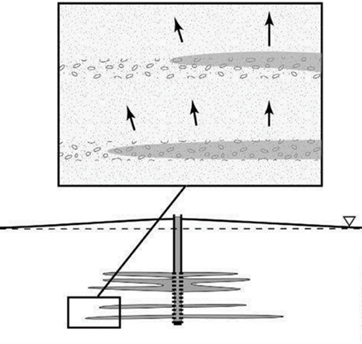
Figure 1 - Aquifer expansion.
Image courtesy of Remediation Hydraulics, by Payne, Quinnan and Potter (2008).
INJECTING COLLOIDAL ZVI
How does the aquifer accommodate injected fluids like colloidal ZVI? It expands, resulting in groundwater mounding (see Figure 1). Injection of colloidal ZVI requires the offset of the injected colloidal ZVI by expansion of the aquifer volume. The colloidal ZVI moves through permeable pathways, and the volume increase is accommodated by the upward displacement of groundwater and colloidal ZVI at higher elevations in the formation. To avoid structural failure of the aquifer matrix, the injection rate must be within the formation’s vertical fluids accommodation potential.
T and the forces commonly applied can exceed the effective stress. We can conclude that injection pressures need to be limited to prevent formation failure—in fact, it would not be a stretch to say this is one of the main failure mechanisms of in situ remediation. To develop a maximum injection pressure (plus a safety factor), the “rule of thumb” equation combines the contributions of vadose zone thickness and saturated zone thickness above the injection point (see Figure 2).
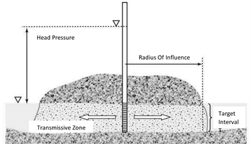
Figure 2 - Combination of vadose and saturate zone thickness.
Image courtesy of Remediation Hydraulics, by Payne, Quinnan and Potter (2008).
Figure 3 shows the structure failure of the aquifer matrix when the vertical fluid displacement is too slow to accommodate the colloidal ZVI injection rate.
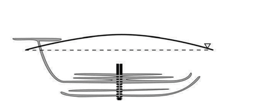
Figure 3 - A too high injection rate resulting in short-circuiting.
Image courtesy of Remediation Hydraulics, by Payne, Quinnan and Potter (2008).
HOW DRILLING METHODS AND LINE LOSSES IMPACT PRESSURE MEASUREMENT AND DESIGN
Sources of resistance to flow other than the formation can confound the ability to monitor pressures applied to the formation. These sources include friction forces in the injection manifold and attached hoses, well screen losses, and compaction of the formation during drilling or well development practices. All contribute to pressures observed at the injection manifold at the surface, which can obscure the pressure applied to the formation at any time.
- Line Loss: Frictional losses calculated for injection manifolds and attached hoses that can be subtracted from pressures at the injection screen
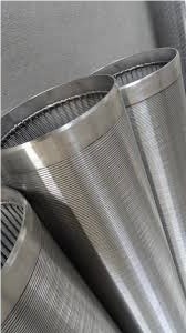
- Well Screen Losses: The pressure through well screens, which can be minimized through proper well design and injection screen materials (see Figure 4)
- Well Development: For injection wells, minimizes pressure losses between the well screen and the formation; wire-wound screen simplifies the well development process
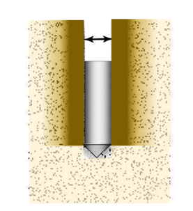
- Formation Compaction: Drilling approaches can compact the formation, significantly increasing the pressure required to push the colloidal ZVI past the borehole wall. For example, with direct push injection, compacting a compressible soil (like silts and clays, which are more compressible than sorted sands and gravels) will require more injection pressure (see Figure 5). Auger drilling can also cause formation compaction.
 |
 |
| Figure 4 - Wire-wund screen. |
Figure 5 - DPT compaction of compressible fine-grained soils. Image courtesy of Remediation Hydraulics, by Payne, Quinnan and Potter (2008) |
INJECTION PRESSURE LIMITS AND FORMATION FAILURE
Injection wells are less efficient than extraction wells because it takes more work to displace groundwater from the surrounding formation. Under extraction conditions, the cone or depression assists extraction through gravitational potential, while the cone of pressure with injection is counter productive to the injection process. Mounding that is created counteracts the injection process, requiring more positive head versus negative during extraction. What this means is that injection wells typically yield 33% of comparable extraction flow rates. Since the hydraulic equations do not account for compressibility or inertia forces under injection, well capacity testing is recommended to evaluate flow versus head requirements need to be developed prior to full-scale remediation.
For injection wells to achieve the same flow rate as extraction wells, special design and construction techniques are required to accommodate the injection pressures and avoid well-seal failures. It is important to note a relatively minor change in injection pressure (less than 5 psi) can result in hydraulic fracturing and formation damage. The water table mound that is created during injection reduces the effective stress in the formation, potentially leading to hydraulic fracturing, if the pressure is beyond the formation’s strength. Unintended hydraulic fracturing can lead to development of permanent flow paths that disrupt the natural flow in the formation.
Under shallow water table conditions, colloidal ZVI can result in short-circuiting from improperly designed injection wells or improperly abandoned borings. Modest injection pressure can provide adequate head to build a water-table mound above the ground surface. In cases where the aquifer consists of multiple water-bearing units, short-circuiting to the shallower units that do not require treatment can occur. At many sites short-circuiting is seen at the surface, creating an obvious problem. However, when the vadose zone is stratified (such as when permeable fill material overlies native aquifer materials), it is possible that short-circuiting occurs below grade and goes unnoticed and the system failure is not detected.
When developing an injection design, there are three potential failure mechanisms to be considered:
- Short-Circuiting: Injection liquids traveling along made-made pathways in the subsurface. Examples include utility trenches, improperly abandoned sampling borings, nearby monitoring wells and the injection boring itself. Even gravity injection, e.g., zero pressure, does not completely prevent injected fluid from traveling along these pathways. If potential short-circuiting is an issue, injection pressures should not exceed the equivalent water column height to the vertical barrier.
- Hydraulic Fracturing: Uncontrolled hydraulic fracturing can occur if the effective stress is reduced where the shear strength of the aquifer matrix is exceeded. When this happens, it is possible to initiate and propagatehorizontal fractures. In homogenous zones, fracturing is initiated through shearing along planes of weakness, while in heterogeneous zones, flow is concentrated in high-permeability depositional features commonly inducing fractures along bedding structures. While fracturing methods can enhance distribution under certain circumstances—like when using micro-scale ZVI solid slurries in silts and clays—the controlled distribution we are trying to achieve is specifically designed to avoid this process.
- Fluidization or Liquefaction: This occurs when the vertical and horizontal effective stresses in the aquifer are reduced to zero through high injection pressures that exceed the overburden pressure of the formation. When this occurs, the grains lose all contact, and the formation stress is reduced to zero. This results in a quicksand condition and the formation is homogenized. Fluidization can be used to initiate fractures with direction nozzles; however, when it occurs under uncontrolled conditions, results are unreliable and counterproductive to in situ injection design.
Design considerations to avoid formation damage and hydraulic fracturing are often based on conventional soil strength analysis, but these assume static groundwater systems that do not consider the concentrated flow associated with injection. Therefore, injection capacity tests for either DPT or well screened intervals are recommended before full-scale implementation. Considering the overall costs associated with remediation—like site characterization, regulatory administration, injection chemistries, and post injection monitoring—it only makes sense to invest in injection capacity testing. Without contact, colloidal ZVI will not be effective, and if injection rates are significantly lower than anticipated, cost will increase without an effective multiple location manifold strategy.
INJECTION CAPACITY TESTING
Increasing injection pressure can induce failure in the aquifer matrices. Because the soil strength relationships do not account for injection flow, and average soil behavior rather than the limiting case, safety factors should be applied to setting injection pressures.
I recommend injection capacity testing to verify flow versus pressure relationships, since the traditional geotechnical approach does not consider impacts on groundwater flow on the soil strength. The traditional approach also relies on the assumption that the formation is homogeneous. In reality, heterogeneities in the aquifer will concentrate flows in the more permeable zones, potentially leading to failure before calculations would indicate.
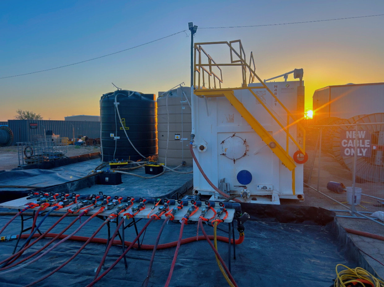
Injection capacity testing should be performed using the estimate range of allowable pore pressure increase as an upper limit of the operating pressure. The test should be conducted like a step-drawdown test, where the injection pressure and flow rate are monitored through several steps in the injection flow. Preferably this is done with automated systems (see Figure 6), where pressure/water level e.g., pressure transducers, and flow rates e.g., mag flow meters, can be monitored and recorded continuously, and repeated so that pressure versus flow rate curves can be developed.
The initial flow rate can be estimated to be 33% of the well under extraction conditions. Then test different flow rates. The test should start at 20% of the design flow rate and ramp up to 80% of the design injection pressure.
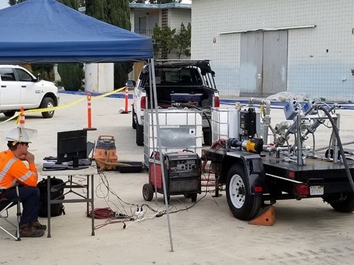
Figure 6 - Injection capacity test with automated system
To ensure contact of colloidal ZVI with contaminants we need to understand what injection pressures and flow rates can be achieved taking into consideration minimization of vertical migration and elimination of any fracturing potential. The best way to obtain these site specific design factors is through injection well capacity testing with equipment that can continuously record and control pressures and flows and mounding. Considering the total life cycle cost of in situ remediation projects, it only makes sense to do our best due diligence to ensure we are injecting chemistries as effectively as possible. Otherwise, there is high potential that contact will not be achieved and post injection monitoring results will not meet expectations and troubleshooting difficult to determine whether site characterization, chemistries, or delivery approach are the route cause of not achieving expectations.
ZVI REMEDIATION RESOURCES
- Not All ZVI is Created Equal: How the Manufacturing Process Can Impact Project Outcomes
- ZVI 101: What is ZVI Emplacement and How Does It Work?
- What is Colloidal iZVI™?
If you’d like to learn more about using ZVI, watch this webinar on-demand. I discuss methods of implementation and optimization, and answer your ZVI questions.


