Thermal Modeling: Science… or Magic?
By: Cascade EnvironmentalThose of you that have been involved in thermal projects may have wondered how the subsurface conditions at your site ties into the rest of the thermal remedy. How is the operational duration determined? What is the design basis for the treatment system? How is the energy usage determined? What’s the foundation upon which the rest of the in situ thermal remediation (ISTR) design is built? In this blog post, we’ll discuss how we use numerical subsurface water and energy balance models to address all of the above.
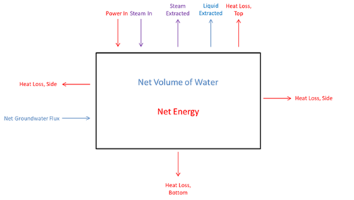
The numerical model approach is a multi-layered, transient box model that tracks how the water and energy balance and heat capacity within the subsurface is expected to change throughout thermal remediation. The conceptual box model of the energy and water balance is shown in Figure 1:

Figure 1 Example of a conceptual box model.
The layered box model approach instinctively lends itself to in situ thermal remediation, since the goal is to understand subsurface processes which are naturally layered and divided according to the geology and hydrogeology. Each layer is treated as its own box through which energy and water is transferred, allowing discrete portions of the treatment volume to be examined more carefully.
The first step in developing a numerical model is to translate the conceptual site model (CSM) provided by the project consultant into input parameters for the numerical model. This requires defining the geometry of the model, i.e. the overall area and volume to be simulated, simplifying the model domain to a collection of 8 to 12 layers, and then defining the subsurface properties of each layer. Key data provided by the consultant that aids in this exercise include:
- Geologic descriptions and cross-sections
- Soil boring logs
- Geophysical and hydrogeologic soil analyses that include estimates for porosity, permeability, moisture content, saturation and hydraulic conductivity
- Electrical resistivity measurements for dominant layers
- Potentiometric surface (water table) maps
- Aquifer tests (slug/pump tests)
- Contaminants of concern and clean-up goals
- Contaminant distribution maps and cross-sections

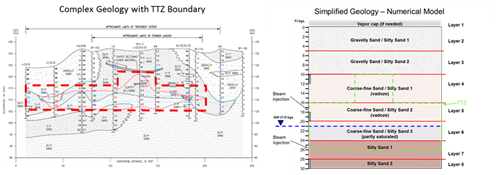
Defining the layers of the model entails assimilating all the data above and determining the optimal subsurface distribution that accounts for natural divides in the lithology, hydraulic boundaries, and the geometry of the treatment zone. This requires simplifying assumptions to create a subsurface representation of the site fit to the model domain. Figure 2 demonstrates how a geologic cross-section (left) may be simplified to the layer distribution shown on the right for input into the numerical model.

Figure 2 Example of how a complex geologic cross-section is transformed into a simplified conceptual model.
Once the subsurface distribution is understood, the porosity, saturation and groundwater flow rate must be defined for each layer. Ultimately, the goal is to understand the total volume of soil, water and air in the model domain and how much groundwater is flowing through in order to estimate the site heat capacity and therefore the energy required to heat the volume to the target temperature.
The outputs include an energy and water balance, heat-up curves, operations duration, treatment design parameters such as target vapor and liquid extraction rates, and estimates of what the project utility use and cost will be. All of these components are crucially influential to the project design, and are used to track project progress during operations. Figure 3 depicts two examples of the observed average treatment zone temperature vs the predicted modeled treatment zone temperature. It shows that though a simplified representation of the treatment volumes, when the subsurface is properly understood the model is an accurate and reliable tool for predicting progress towards target temperature.

Figure 3 Examples from two different projects of modeled vs observed temperature.
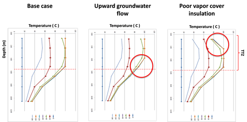
The numerical model is also useful in the design phase for investigating potential challenges, such as ground water flow at certain depths, the importance of the R-value of a vapor cover, and sensitivity to starting groundwater levels and saturation. By simulating high and low values of key factors, sensitivity studies are developed that indicate where to focus and optimize the design. Figure 4 is an example, where the upward flow of groundwater and a poor vapor cover led to less than optimal temperature profiles.

Figure 4 Temperature profiles modeled for a site (left), along with two scenarios where groundwater flow (middle) and a poor vapor cover (right) causes less than ideal heating. Sensitivity studies are used to optimize the design and to prevent realizing these conditions.
Overall, the thermal model provides a solid baseline for our clients and engineers to know what to expect during a project and when operations are not going according to plan. It is used to verify and inform the design, to track the progress of a project during operations, and to reflect on how a project performed relative to expectations throughout its operation.

